Introduction
Our rowing club organizes regular rowing matches and a number of years ago, we switched from manual stopwatches to RaceClocker for our timing. As we do our timing on bridges for our Bridge to Bridge Race, we primarily use phones for our timing. Tapping on a phone screen is not ideal for timing and we already had an alternative in place with a programmable Bluetooth button. This works fine with a couple of drawbacks. If the phone goes in standby, the button might not reconnect and Bluetooth LE does introduce a small delay when sending the keyboard command.
Enter a new idea: Let’s use a wired USB keyboard emulator button instead!
First task, check which ESP32 is best suitable for this task: The Seeed studio Xiao ESP32 S3 can emulate USB keyboards quite nicely and has a small (enough) footprint. Next step was to select a button which is sturdy enough. Initially I wanted to go with a separate button and LED indicator but found some really nice buttons at TinyTronics with integrated LED ring.
I then spend several hours/days to design and finetune a housing for both the button and ESP32 board.
Required parts
- 3D printer and a filament of your choice (I use PLA+)
- STL files for the housing:
- Soldering station
- Small self tapping screws M2.3 * 5 mm (you can use M2.3 * 8 mm for the longer end)
- Heatshrink tube (2.5 / 3 mm thick)
- Seeed Xiao ESP32 S3, companies I use are:
- Windows/Mac computer with Arduino IDE for programming the ESP32
- Hardware button with integrated LED (either choose the RGB version (button and connector sold separately or the mono LED version (button and connector combined).
- Button with RGB LED: https://www.tinytronics.nl/nl/schakelaars/manuele-schakelaars/drukknoppen-en-schakelaars/metalen-drukknop-16mm-verhoogd-reset-met-3-6v-rgb-led
- Connector for RGB button: https://www.tinytronics.nl/nl/kabels-en-connectoren/kabels-en-adapters/overige/connector-kabel-voor-metalen-drukknop-16mm-met-rgb-led
- Button with green LED (with connector): https://www.tinytronics.nl/nl/schakelaars/manuele-schakelaars/drukknoppen-en-schakelaars/metalen-drukknop-16mm-verhoogd-reset-met-3v-groene-led
- Foam grip with internal diameter of 28 mm
Assembly
- Print the 5 parts from my Thingiverse page. Note: The button conn tool and button nut tool are assembly aids and only need to be printed once (unless you misplace them).
- Cut the foam grip to size (if you ordered the longer version) and slide/wrestle it onto the housing. Leave a bit extra as it tends to stretch when you push it on, you can push it to the correct length later.
- On the bottom side of the button, mark where the red wire(s) of the connector need to go
- Put the rubber seal ring on the button and insert it into the hole of the housing.
- Use the button nut tool to screw the nut onto the button
- Download the latest firmware file:
- Start the Arduino IDE, connect the ESP32, select the correct USB port and upload the firmware.
- Solder the connection lead wires to the ESP32 board and insulate them with the heat shrink tubing. Refer to the wiring diagrams for the correct connections.
- Using the button connector tool, push the connector onto the button.
- Note 1: Always check the proper orientation first!
- Note 2: The tool is usable for both the mono connector as well as the RGB connector, make sure to use the correct end.
- Note 3: I actually cut off the restrain clip of the RGB connector to get it off/on more easily.
- Test if the button works correctly
- Slide the ESP32 board into the ESP32 holder (there is a cutout for the Bluetooth connector)
- Slide the bottom plate onto the ESP32 holder and make sure to align the USB connector properly. Note: I superglue the holder and plate together to add some extra rigidity and easier assembly of the bottom plate into the housing.
- Wiggle the bottom plate into the housing and line up the holes of the housing with the holes in the ESP32 holder. Push the foam grip to the side and screw the holder onto the housing
- Double check if all is working fine!
Wiring diagram
Mono LED button version:
- White & Black wire => GND
- Yellow => D1
- Red => D2
RGB LED button version:
- Yellow (NO) => GND
- Red (3) => 3V3
- Green (C) => D1
- Black (2) => D2
- Red (1) => D3
- Black (4) => D4
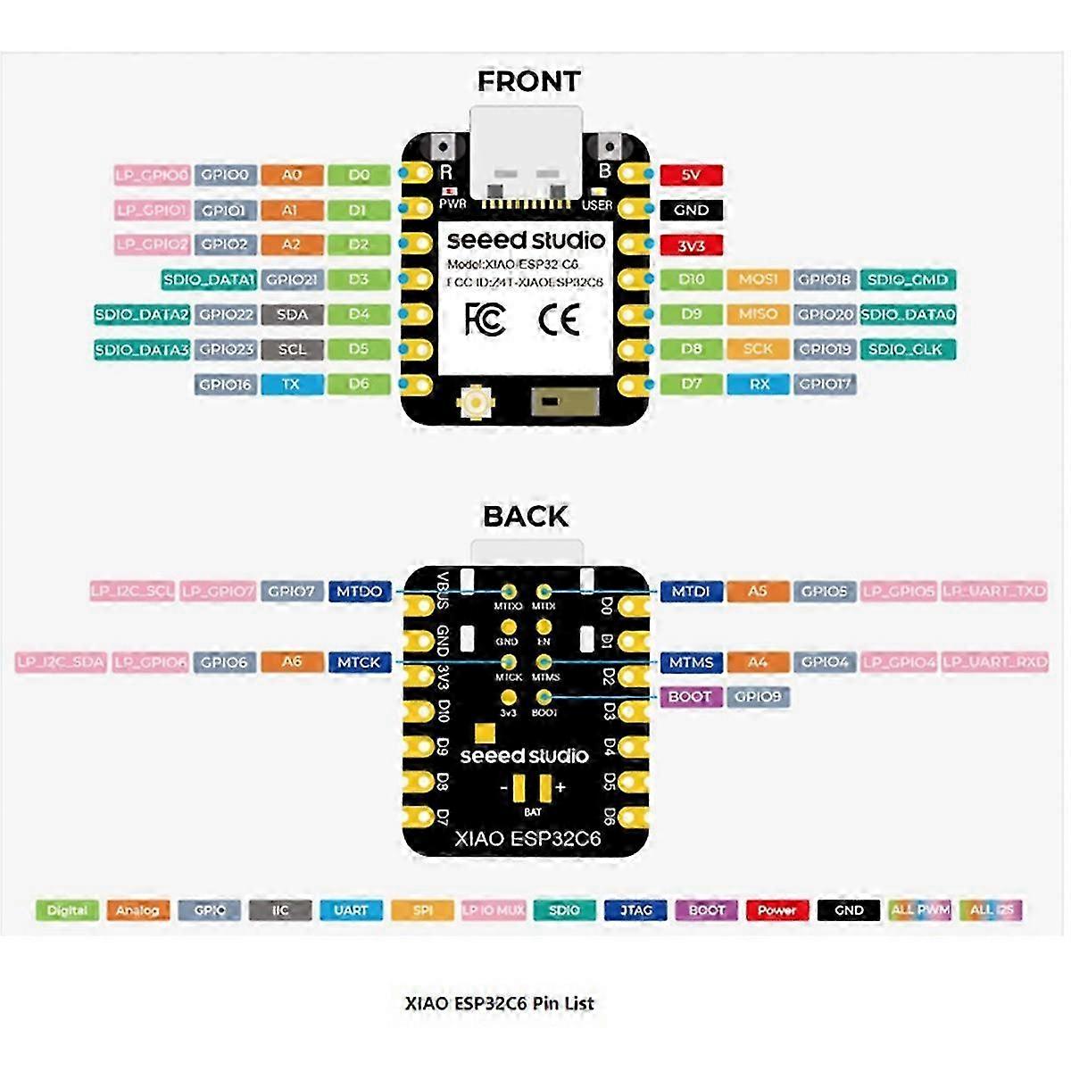
Firmware versions
Mono colour button version
1.0 Initial version
1.1 Added bootloader option to update firmware
1.2 Added USB descriptor for firmware version identification
1.3 Added USB host detection upon startup
RGB colour button version
1.0 Initial version
1.1 Added USB host detection upon startup
1.2 Changed USB host detection to magenta, button press to blue, red blink for bootloader warning
1.3 Added LED “bulb” test upon startup, sequence is red, green, blue, magenta